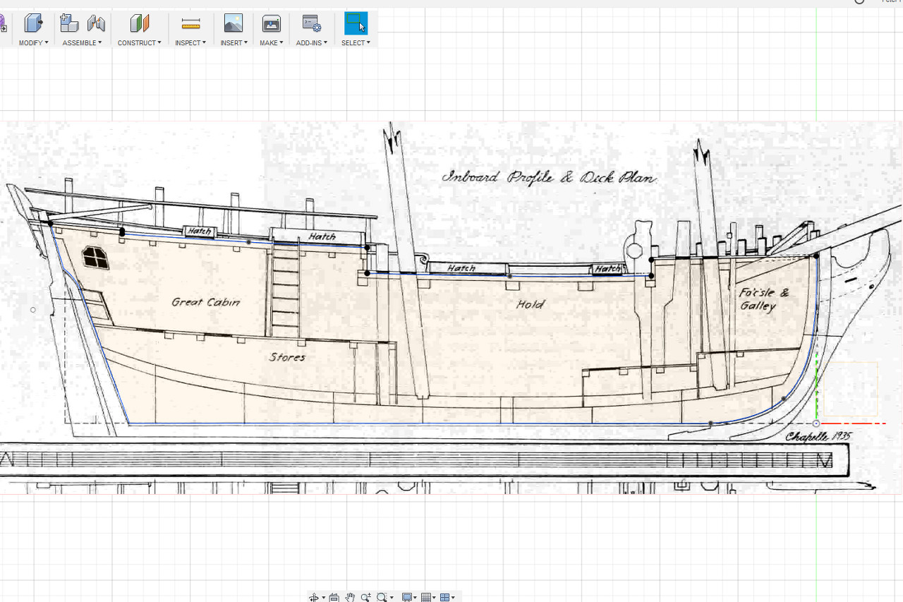
The next thing I need to figure out is the exact placement of the decks and the deck camber. I bring up the inboard profile image. Starting a sketch in the centerline plane, I trace the lines along the underside of the planking on each deck. The lines for the two innermost decks (main deck? and quarter deck?) are very slightly curved. The other two are just straight lines. The sketch continues alone the rabbet and back to the start. I’ll be using this sketch for the false keel laser cut piece. Notches for bulkheads will be added to it later.
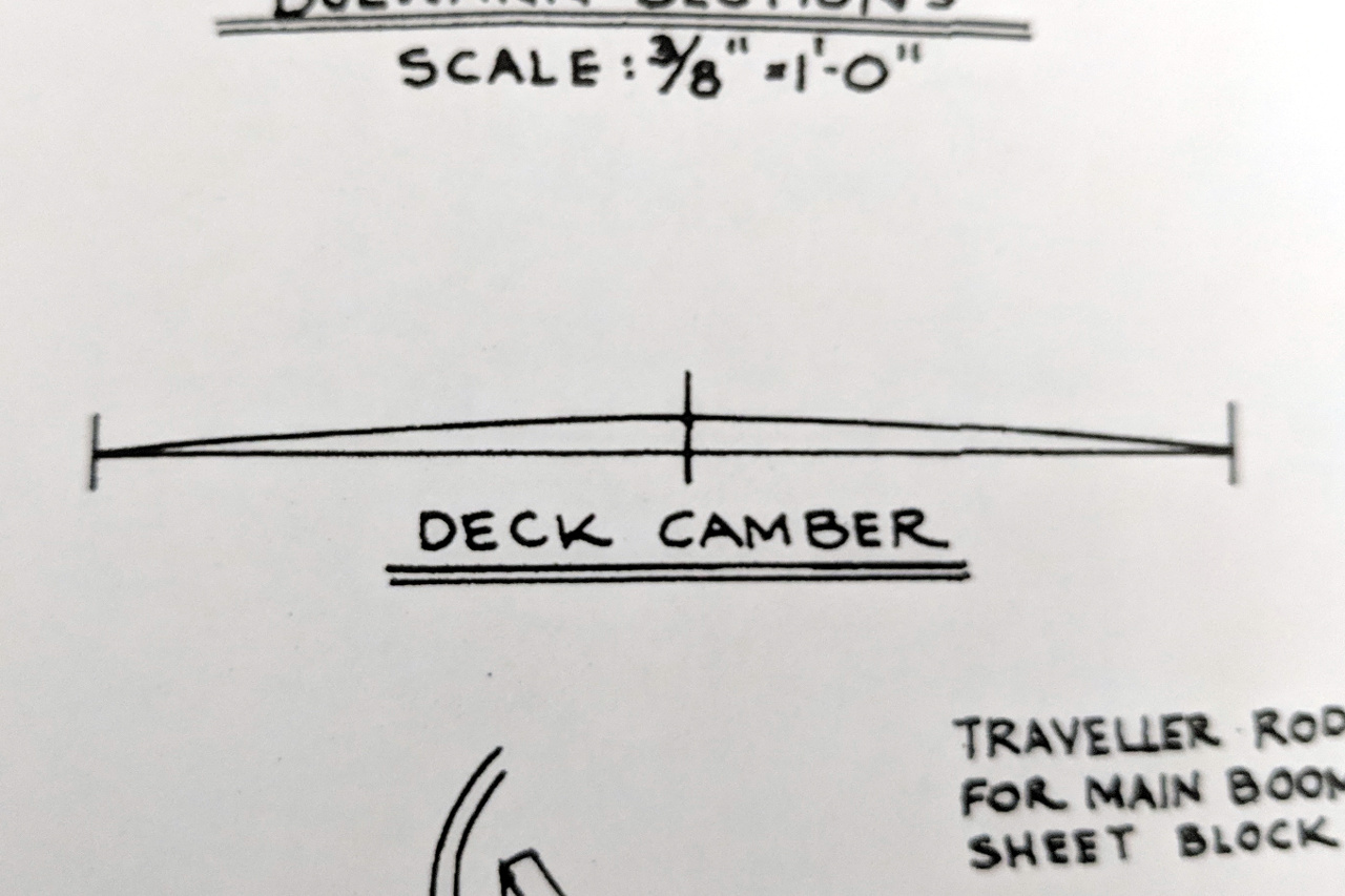
The deck camber isn’t obvious from the Chapelle plans. On the Model Shipways plans, there is a diagram showing an arc over a span of 72mm with the highest point of the arc at 2.5mm. I assume this is the camber at the widest part of the deck, but can be applied overall.
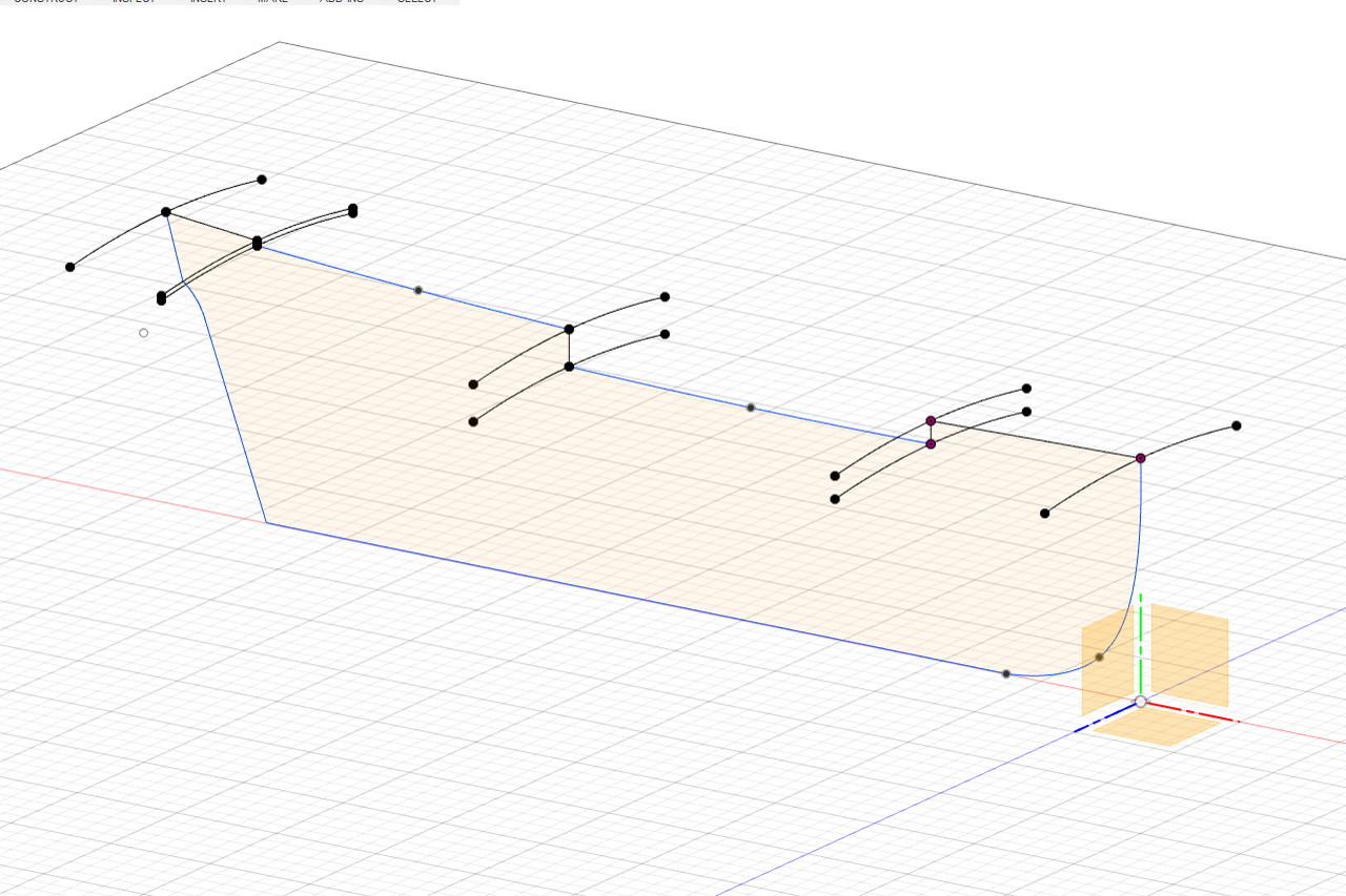
Applying those measurements, I create arcs on the 3D model passing through the start and end points of each deck.
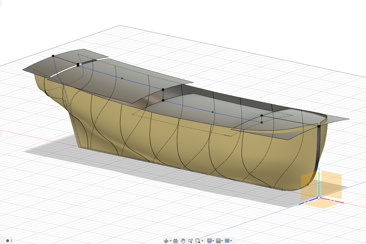
Surfaces are lofted across the arcs. For the two larger deck sections, the line of the deck along the centerline is used as a rail, because it’s curved. That gives those deck sections a very slight saddle shape.
(This picture makes it look like I’m creating a solar-powered ship. 🙂)
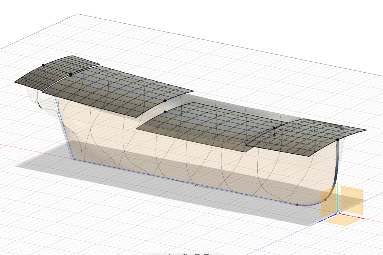
Here are all the surfaces to this point.