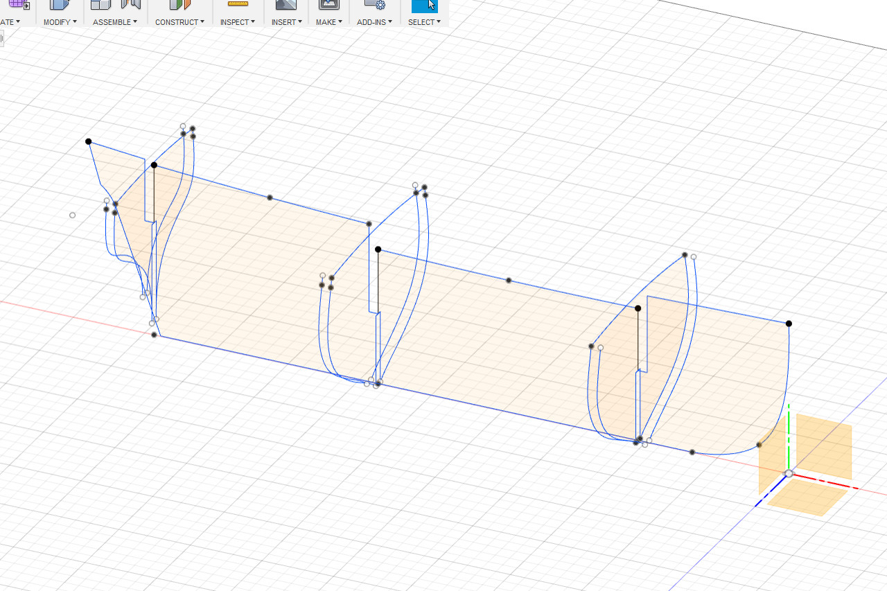
Finally I will start to find the shapes for some bulkheads. I know that I will want bulkheads at the three points where the deck level changes, so those seem like good ones to start with.
I start by making the inboard profile image visible, since it shows the internal structure. Via the construction menu, I create an offset plane at the point where the forecastle deck drops down to the main deck. It’s 52.7 mm back from the forward perpendicular.

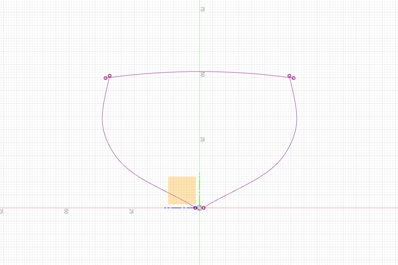
Next I make the hull and deck surfaces visible. I select the offset plane and go to Sketch -> Project/Include -> Intersect. As I move my mouse pointer over the surfaces, anywhere the offset plane intersects with a surface, the intersection curve displays as a red line. I’ll click to select the first intersection curve.
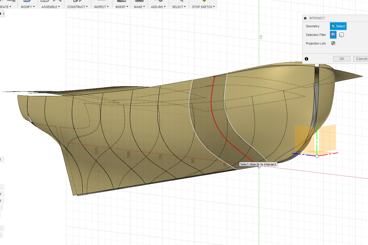
And the one across the deck.
And finally the one on the other side of the hull.
When I click Ok the three curves are saved as a new sketch.
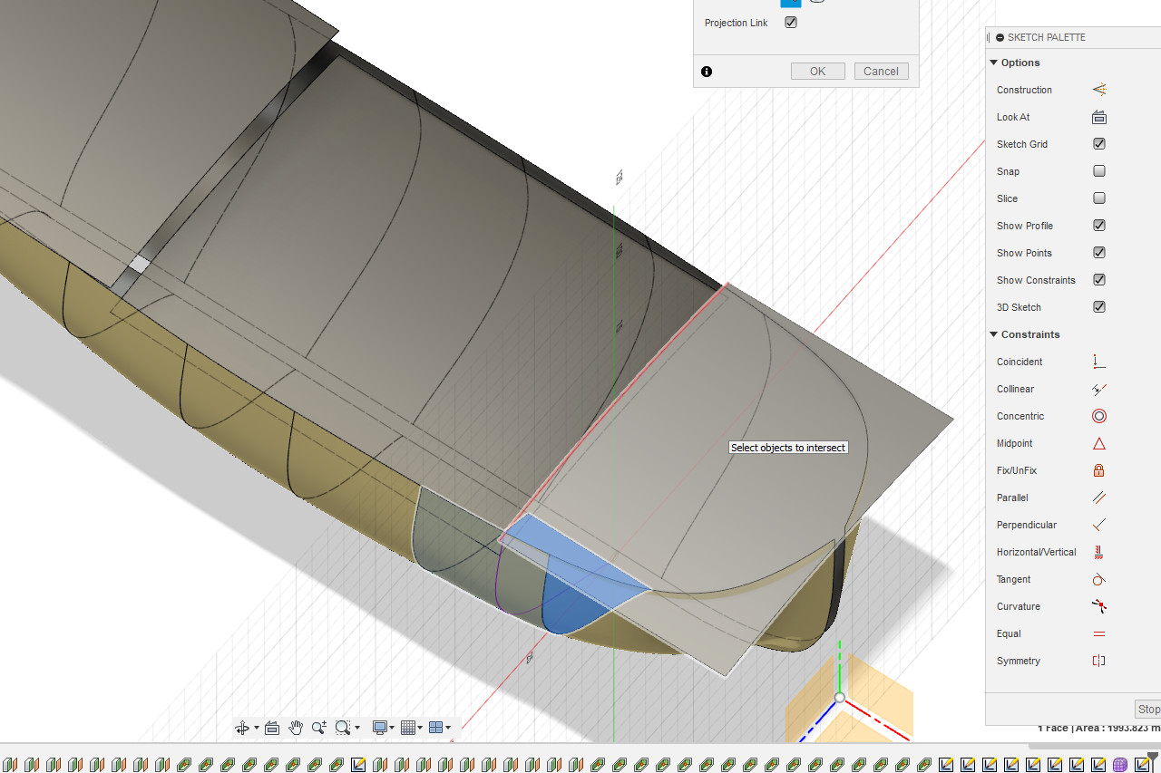
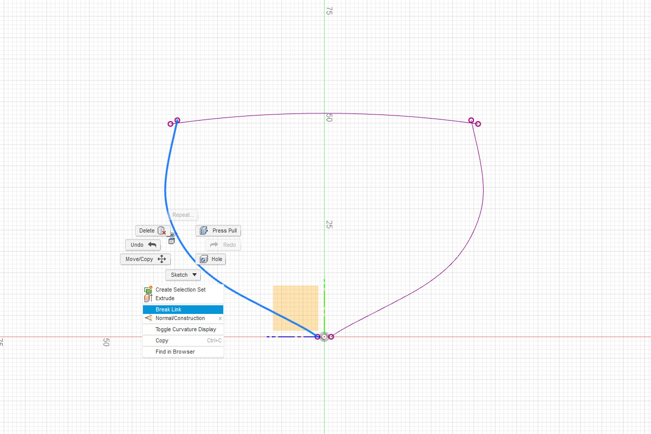
There is some overlap where the deck and hull lines meet. To edit the sketch any further, I have to break the link between the intersection curves and the surfaces. I select a curve, then right click and select Break Link. This is repeated for each curve. The curves change from purple to blue.
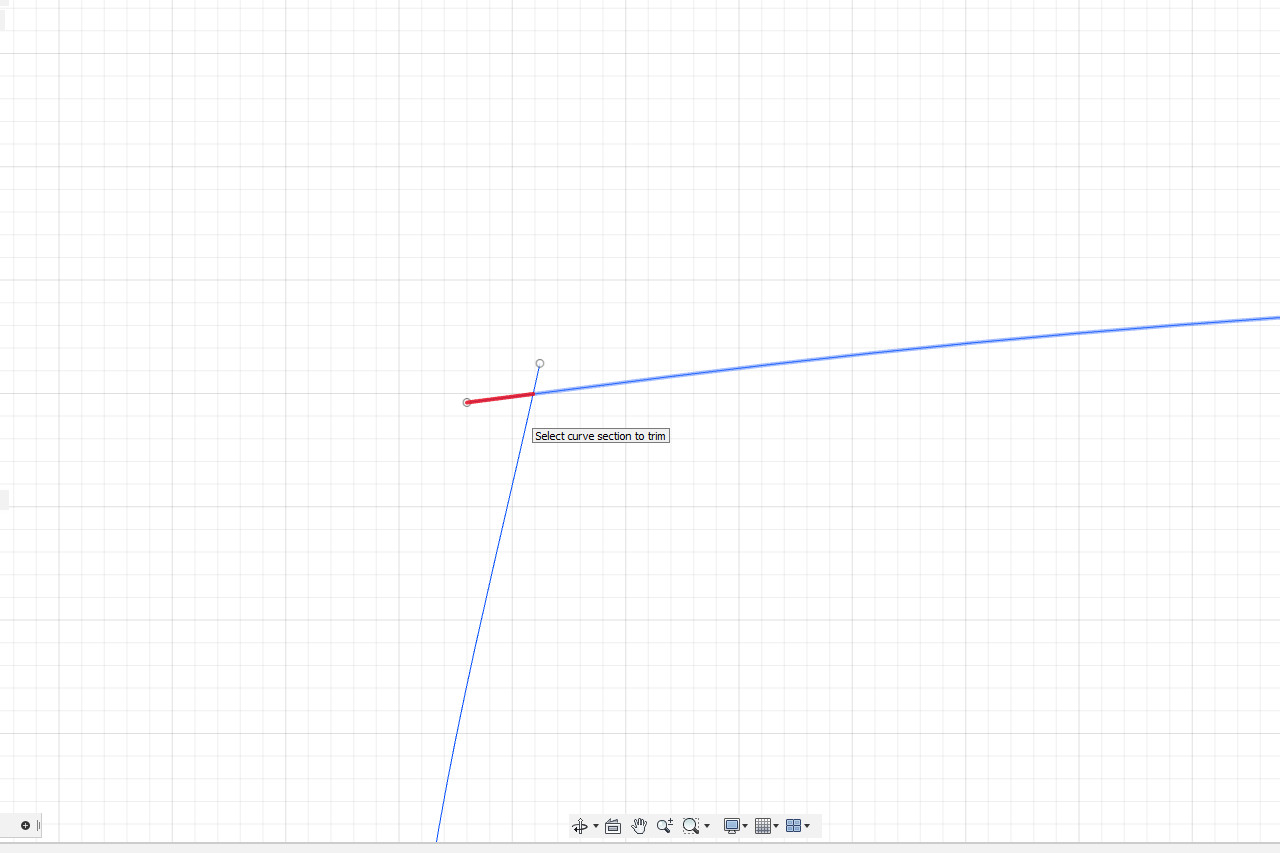
Now I go to Sketch -> Trim. When trim is active, segments of lines in a sketch that can be trimmed will turn red when the mouse pointer is over them. I trim off all the overhangs.
And I add a notch 25mm above the baseline.
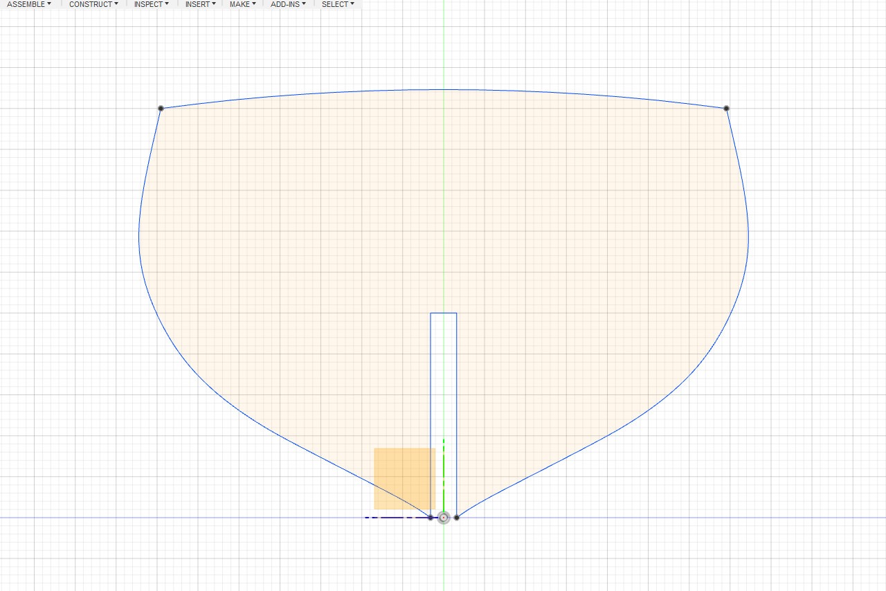
The first bulkhead is complete. I can right click on the sketch, choose Export to DXF, and import the shape into laser cutter software.
Of course, I need to add a matching notch to the false keel.
I would also like to add fairing lines to each piece. The procedure is the same, but I don’t need to include the intersection with the deck surface, and there is no notch.
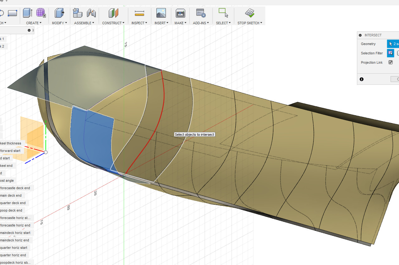
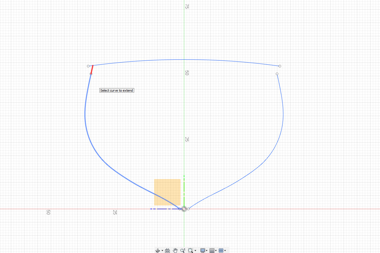
For the other bulkheads at places where the deck level changes, I follow the same procedure. For the second bulkhead, the hull lines don’t quite reach the deck curve. In this case, I first use Sketch -> Extend to extend the lines, then use Trim to trim any overhang.
I edit the false keel sketch and add notches at the appropriate locations for the three bulkheads I’ve created so far.
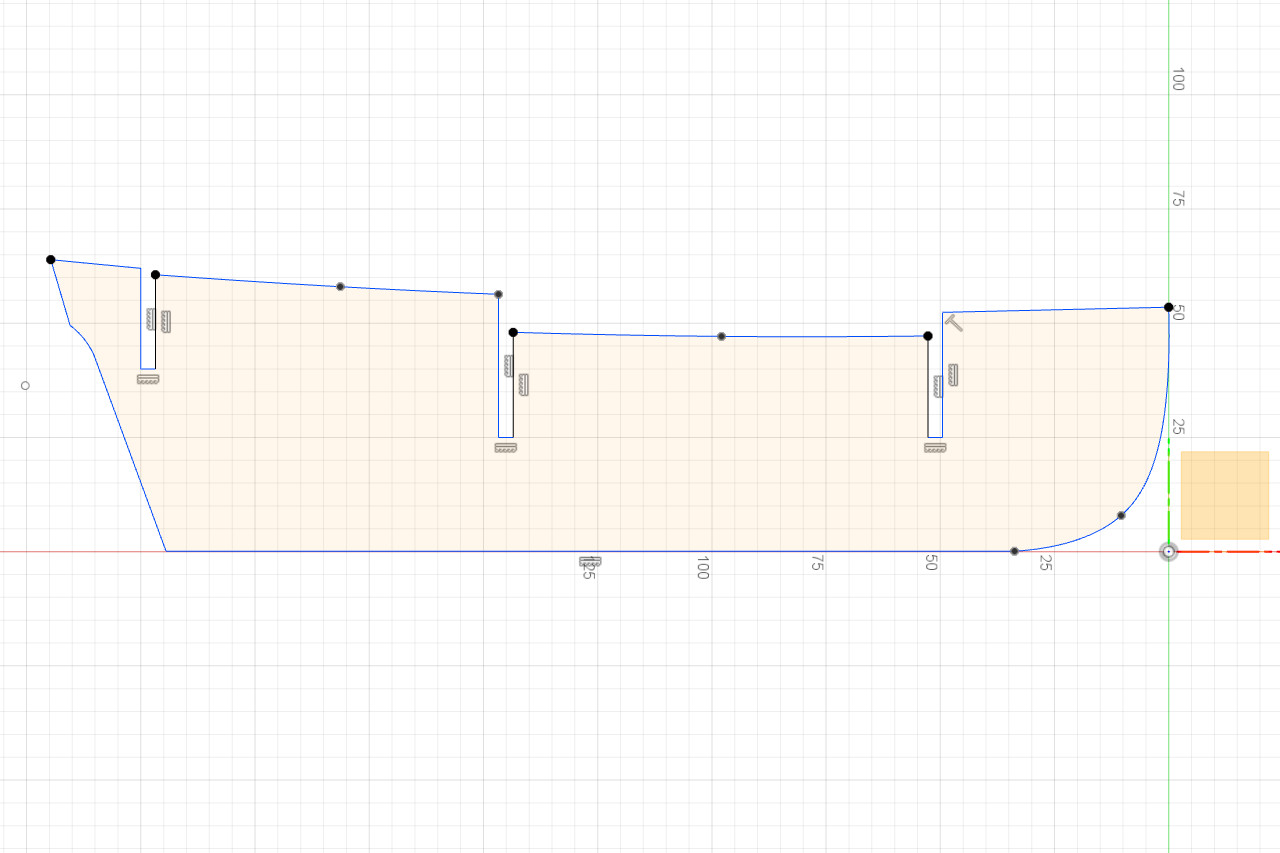
And here’s a view of all the sketches defined in this session. All of these will be exported for use on the laser cutter.