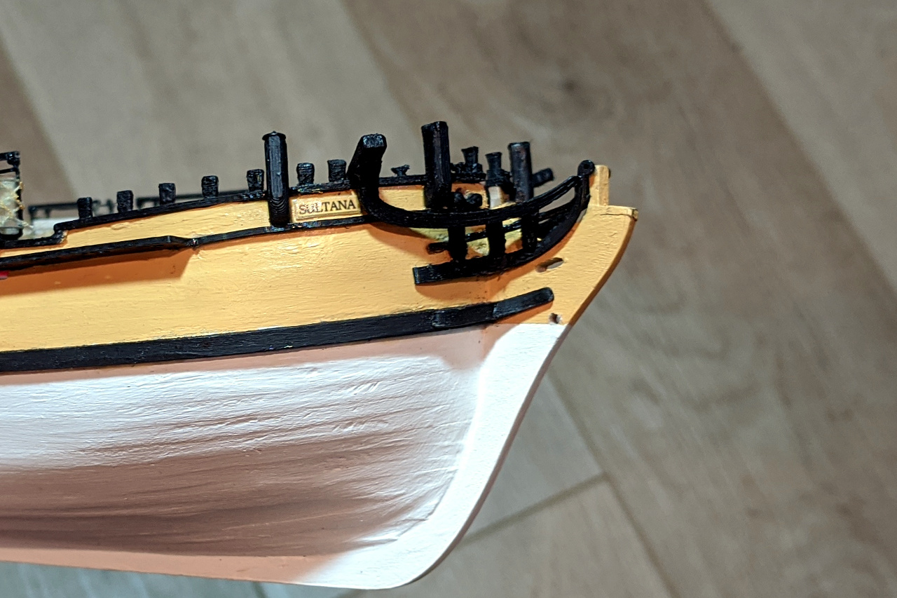
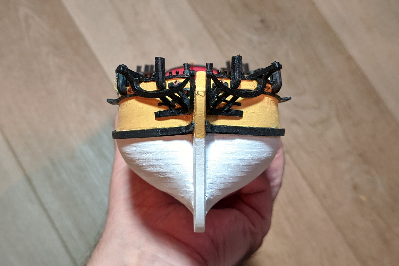
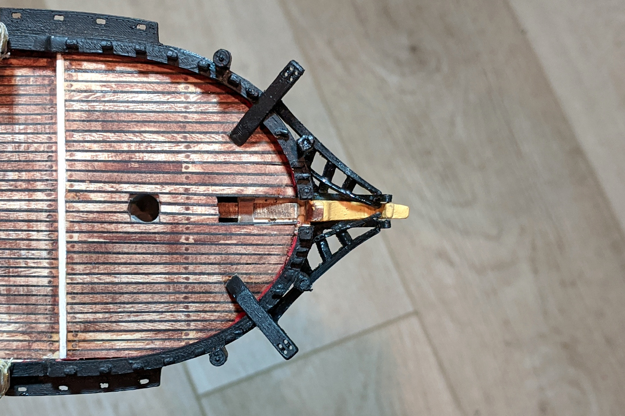
I have completed the head rails, head timbers, and cheek knees. I found it best to work on the cheek knees first, and head rails last. It was necessary to make several parts in multiple pieces, as the shapes were too complex to model as one. I also attached the printed nameplate to the outer bulwarks.
Here is the 3D design for the various 3D printed parts.

For the curious, here is how I created the shape of the headrail in Fusion 360.
I started by creating a construction plane which passes through the underside of the cathead at one end, and through the stem at the other. On this plane, I created a sketch and drew the curve of the headrail. This curve passes through the center of the eventual part.
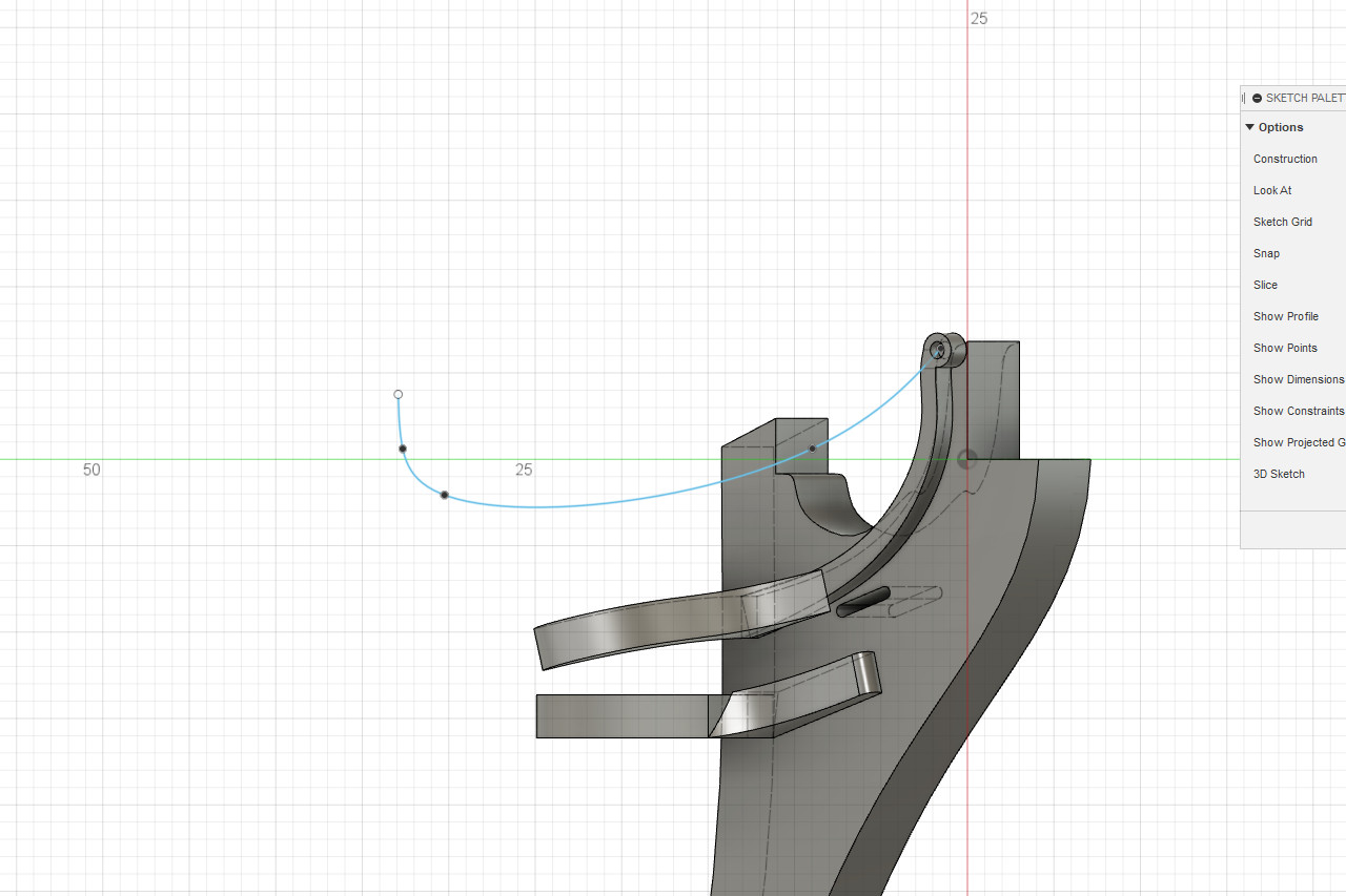
Next, I created two construction planes. The planes are tangent to each end of the headrail curve. On the planes, I created the start and end shapes for the cross-section of the headrail. In this case, a 3mm x 3mm square at one end and a 1mm x 1mm square at the tip, highlighted in blue below.

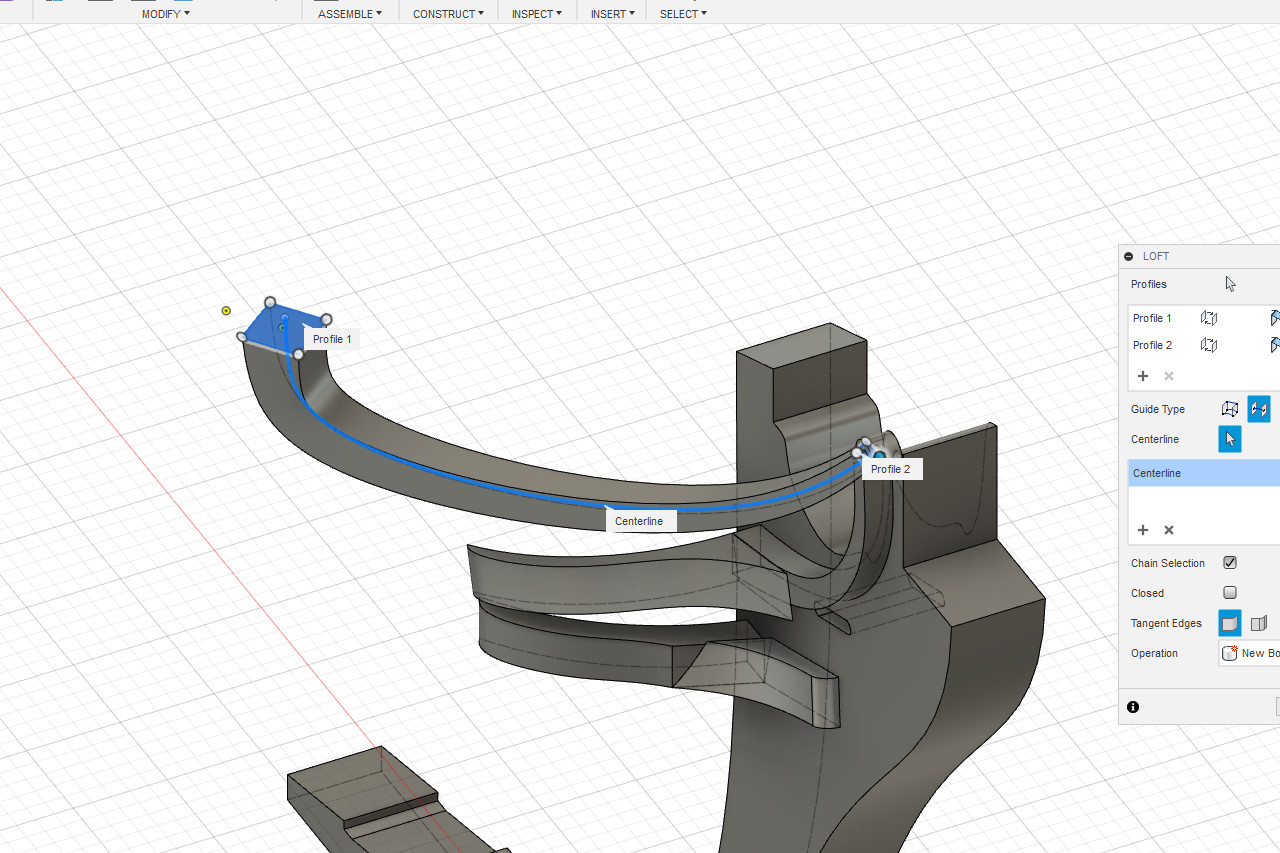
To create a shape, I used the loft tool. Initially, the loft connects the two profiles via a straight path.
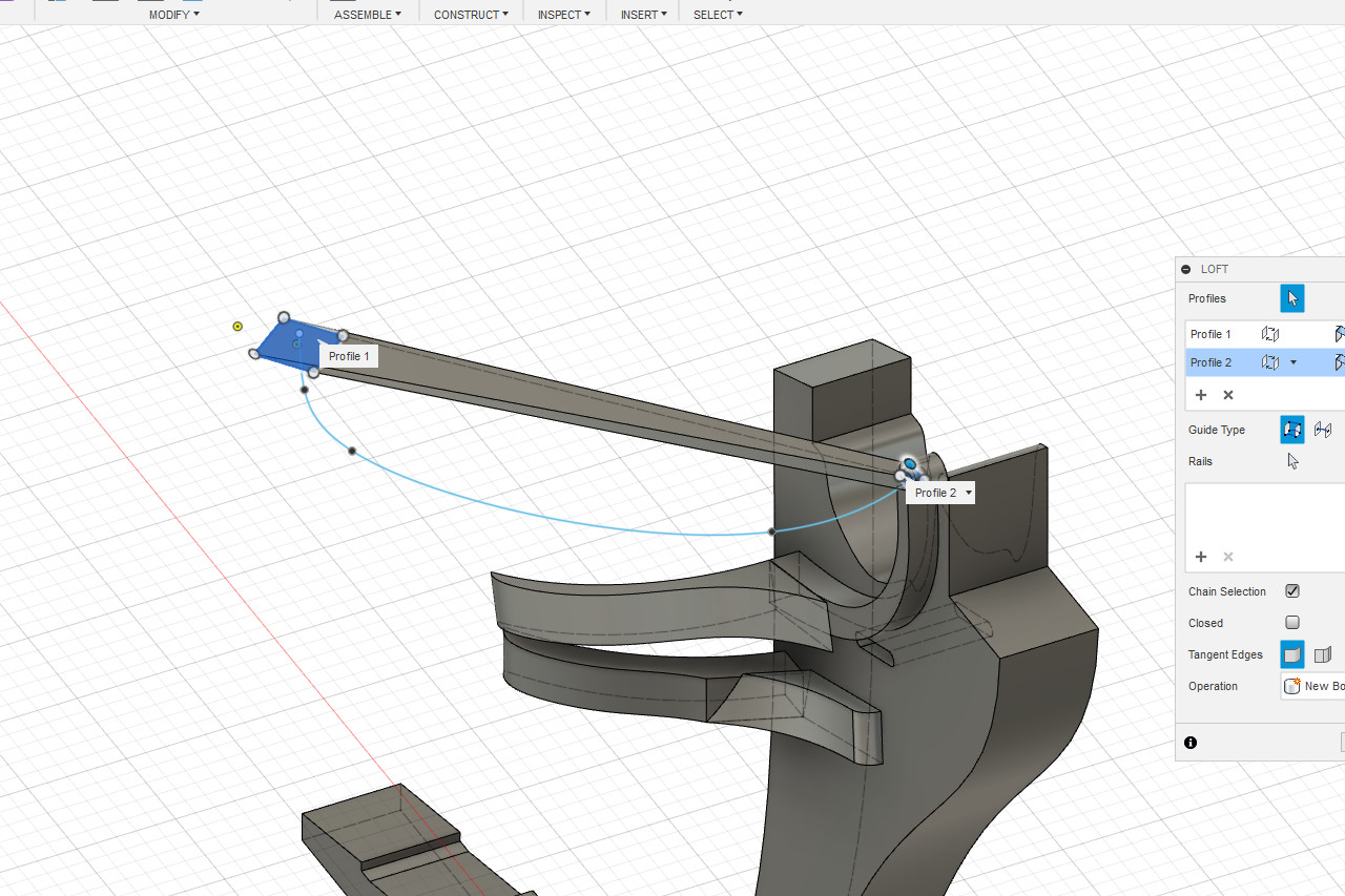
In the loft dialog, I changed the guide type from tails to center line. I selected the headrail curve as the centerline, and the curved shape is created as I wanted it.