More design changes.
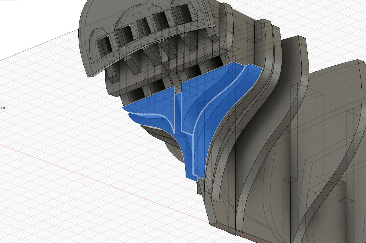
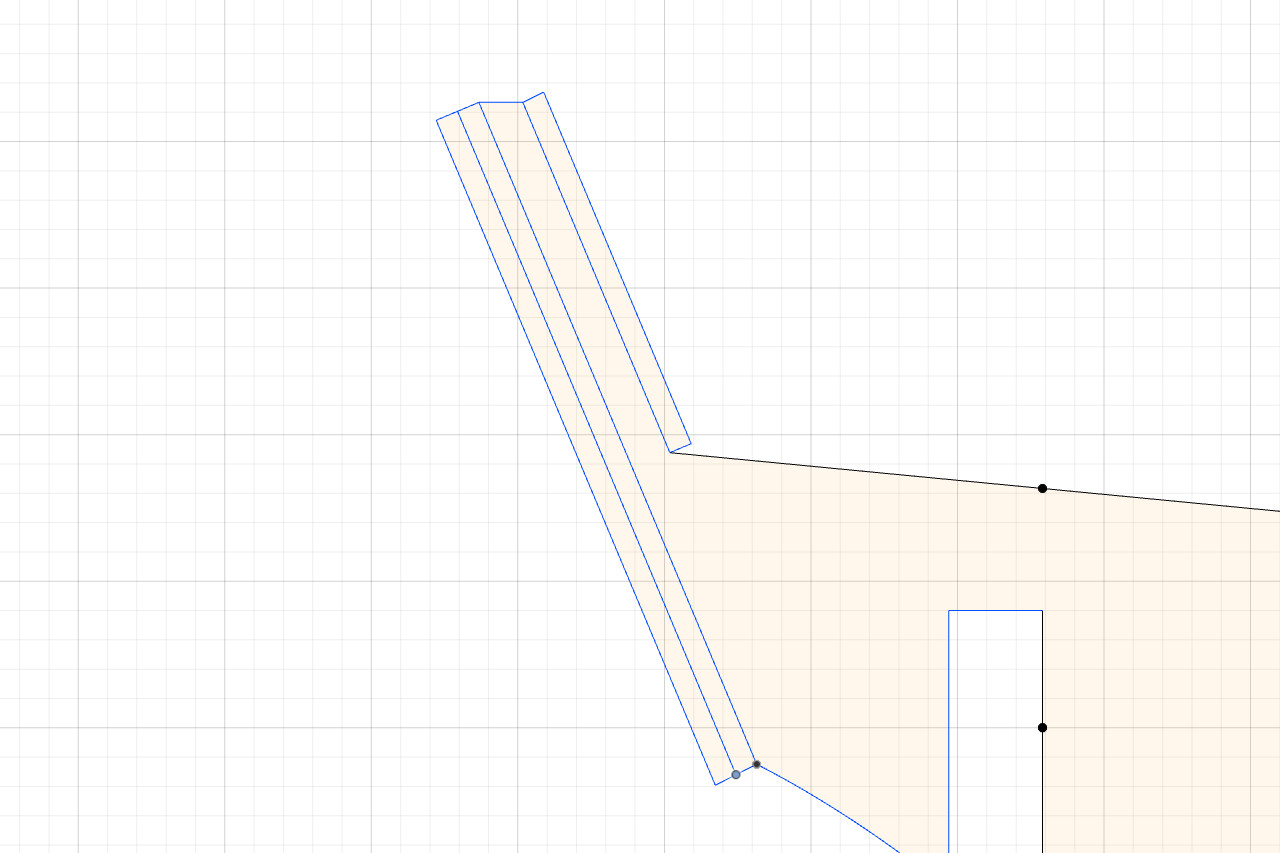
First, I was concerned because there was no surface under the counter for the end of the hull planks to sit on. So, new shapes were added there. The new pieces are highlighted in blue in the picture.
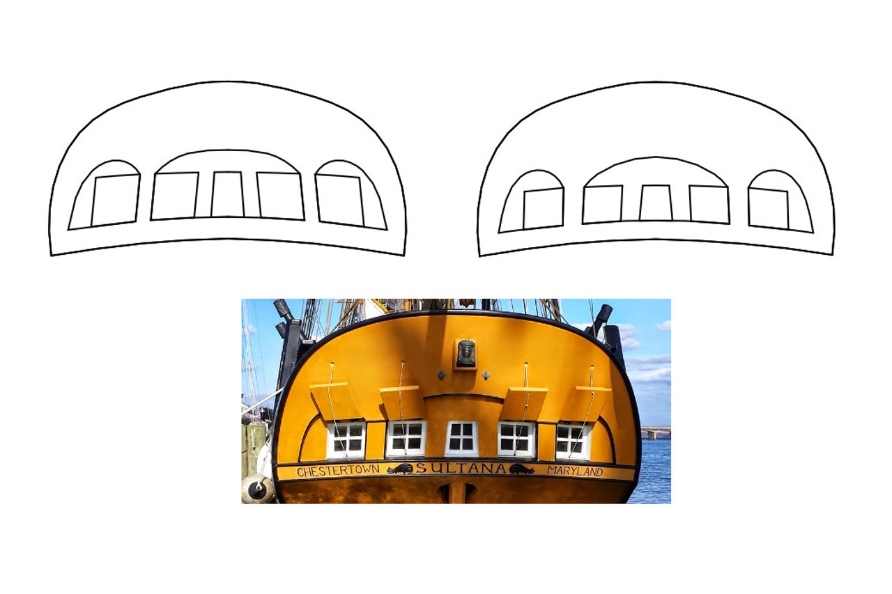
I was not happy with the transom windows, recess, etc. I spent some time redesigning the shapes and it now is closer to what’s in my reference picture. Original attempt is on the left, new version is on the right.
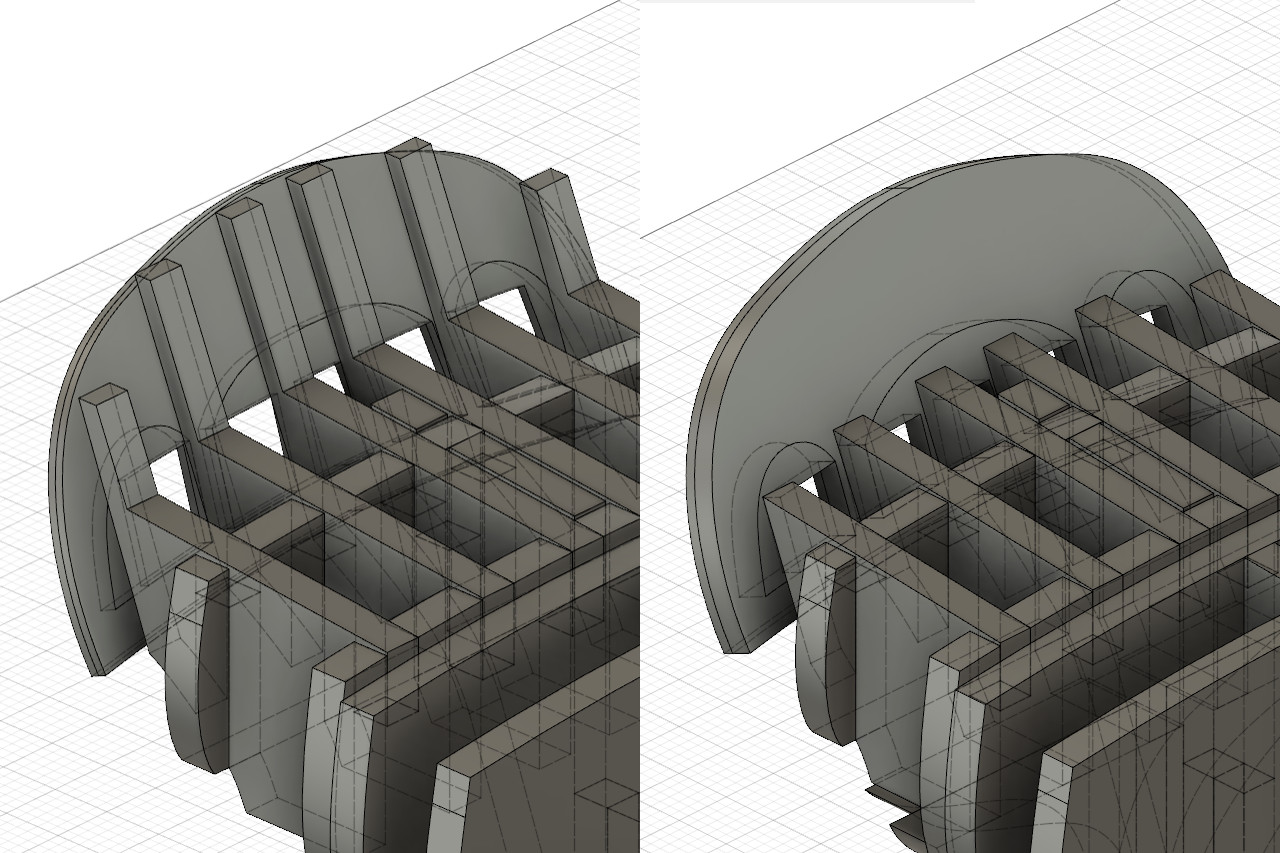
Originally I planned to glue the transom end piece above to simulated stern timbers, and also add some planking to cover the stern timbers on the inside. See the basic idea in the picture below. All those layers together is pretty thick, and trying to make the stern timbers thinner would only make then so thin that they would break easily.
I realized that I don’t need the stern timbers at all. There is already enough surface area for the pieces to be glued on, so the stern timbers were removed from those pieces. Instead, I will cut 3 transom pieces from 1/32″ sheet: one with the recess pattern and two with the windows cut out. This stack will be glued directly on the back, very much as in the original Model Shipways plans.