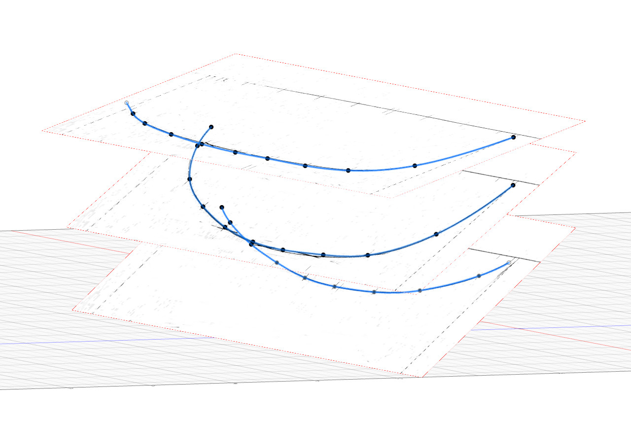
The sketching of lines continues with finding intersection points and then sketching fit point splines through those points. Here are the intersection points for the two waterlines, with the waterline planes visible.
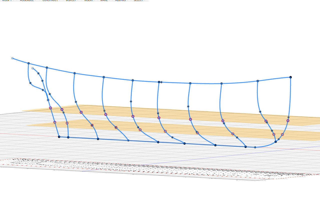
And then the splines. Drawing the lines is easy — just a matter of connecting the dots with a fit point spline and a little adjustment of the curves at the end.
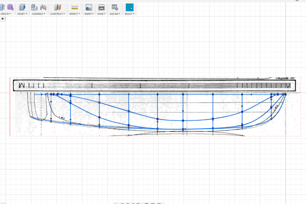
The same procedure is followed for the load waterline. But wait… The intersection points don’t seem to match up to the line on the plans. Is this an error in the plans?
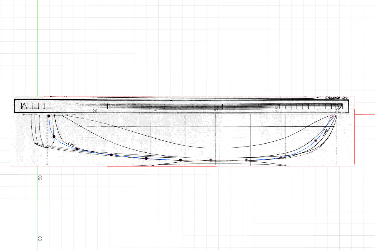
No. This is because of how sketches work in Fusion 360. When you start a sketch, you choose the plane on which it will be drawn. Then Fusion 360 brings you to a view that is tangent to the drawing plane. Because the load waterline is tilted a little off horizontal, the view isn’t directly down onto the plans. Instead, it’s skewed a little, so the view doesn’t match up. The load waterline drawn on the plans is a projection of the hull line down onto a horizontal surface, so to see it correctly, the view needs to be changed so that the viewport is looking directly down. See the view from directly overhead below.
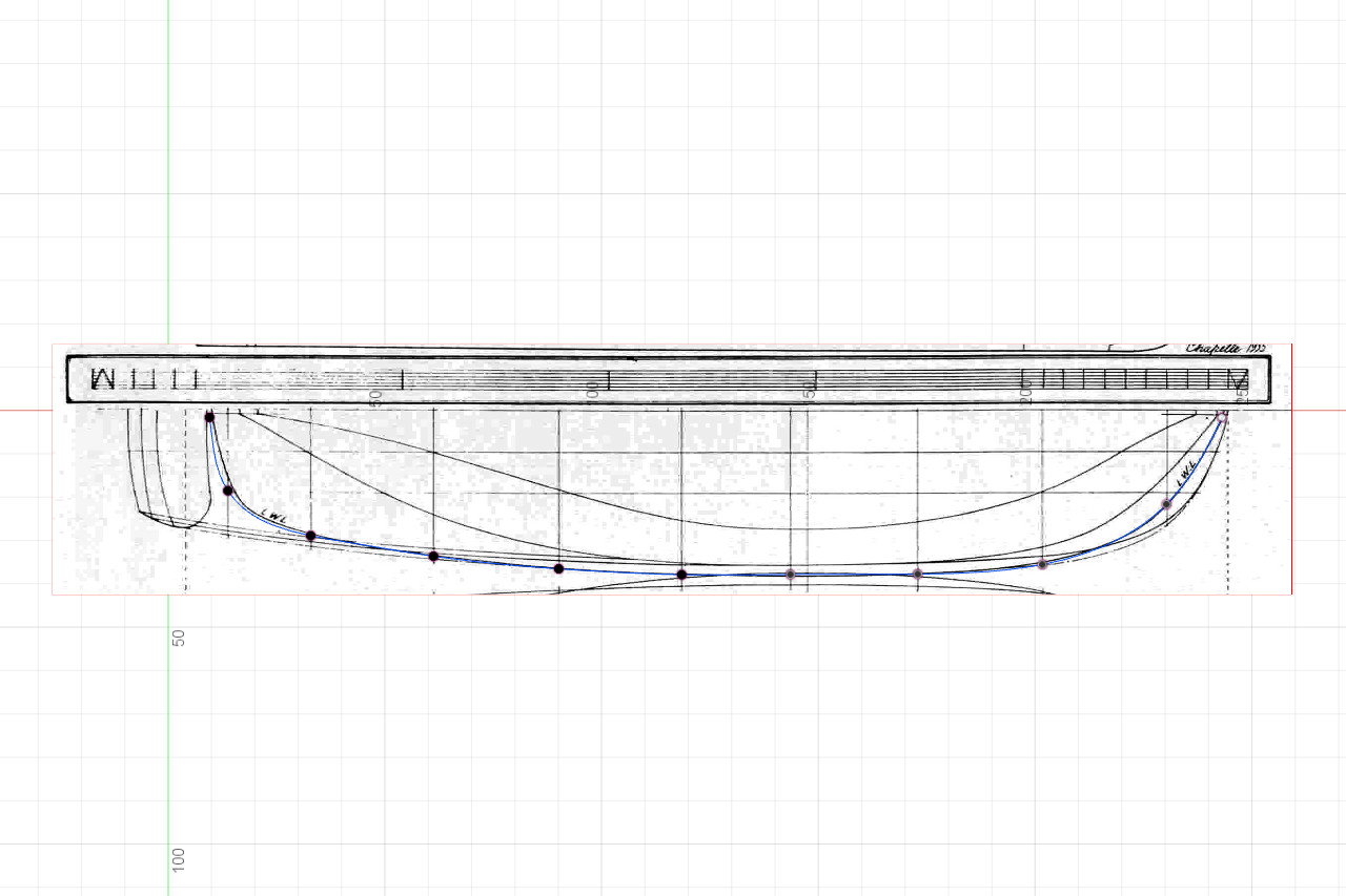
The aft-most portions of the load waterline curve don’t quite match the line on the plans. That is an issue with the plans, as the intersection point is correct in the sheer view. I think it’s close enough not to matter much.
Do diagonals work like the load waterline? Are they projections down onto a horizontal surface? No, they really do get drawn directly on the tilted planes.
Here are all the lines at this point.
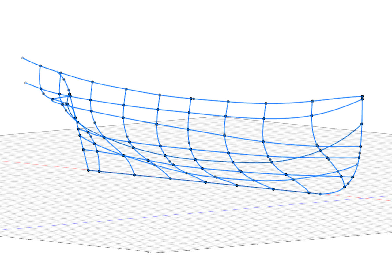
Now it’s finally possible to create the hull surfaces.