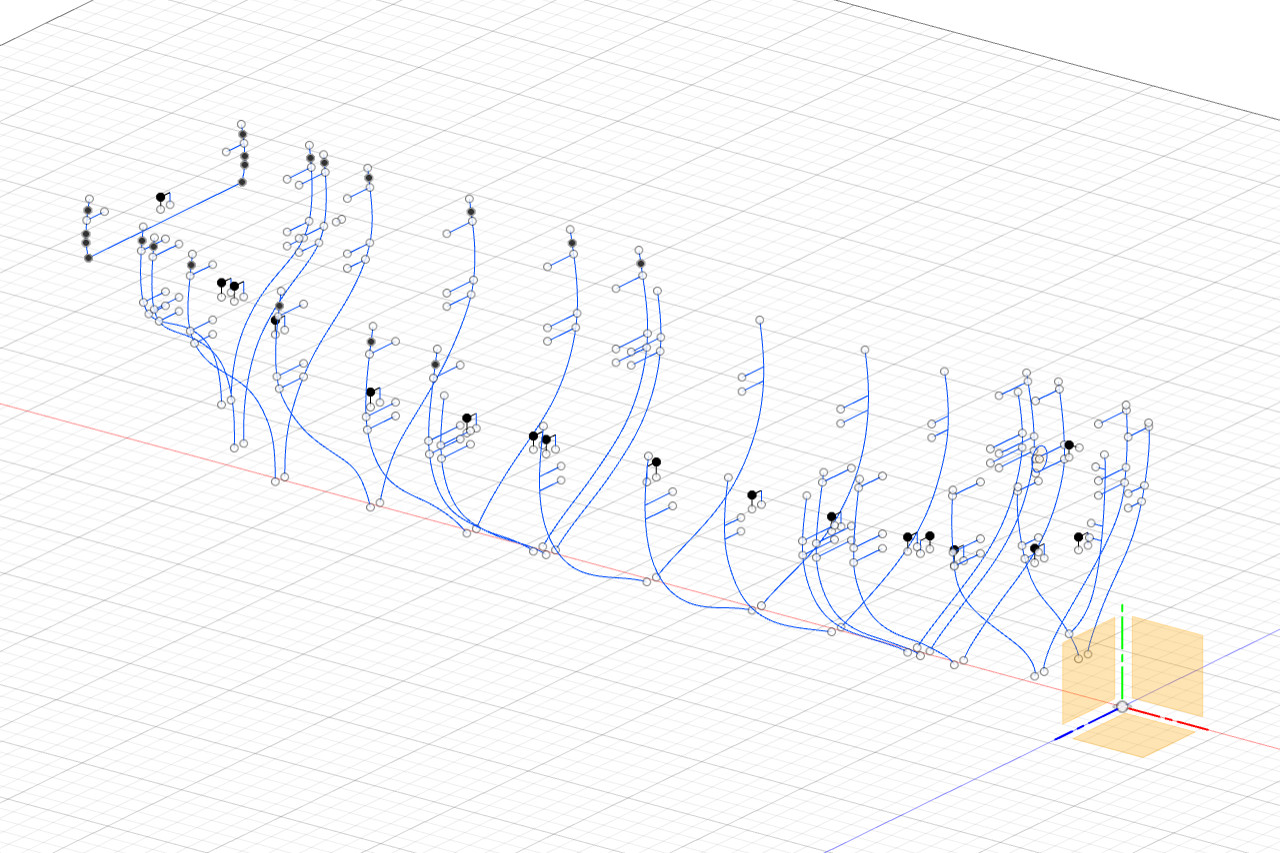
Reference marks were added to the scribe lines for each bulkheads (in the same sketches where the fairing lines are drawn). These reference marks indicate the location of the wales and the bottom of the bulwarks on each bulkhead.
Next I turned to the end piece for the transom. After some careful measurement, I determined that the transom outline on the Model Shipways plans seemed to be properly sized. I scanned the image and brought it into Fusion 360. So far so good.
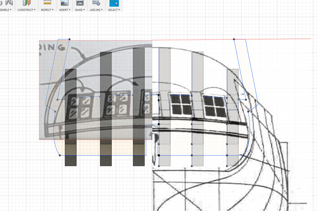
In this image the Model Shipways transom is on the left, and the Chapelle transom on the right. The general shapes are similar, but the MS transom windows are larger and spaced further apart. Also, on the MS transom the lines for the recessed portion of the transom are higher. (There are also some symmetry issues with the MS drawing.)
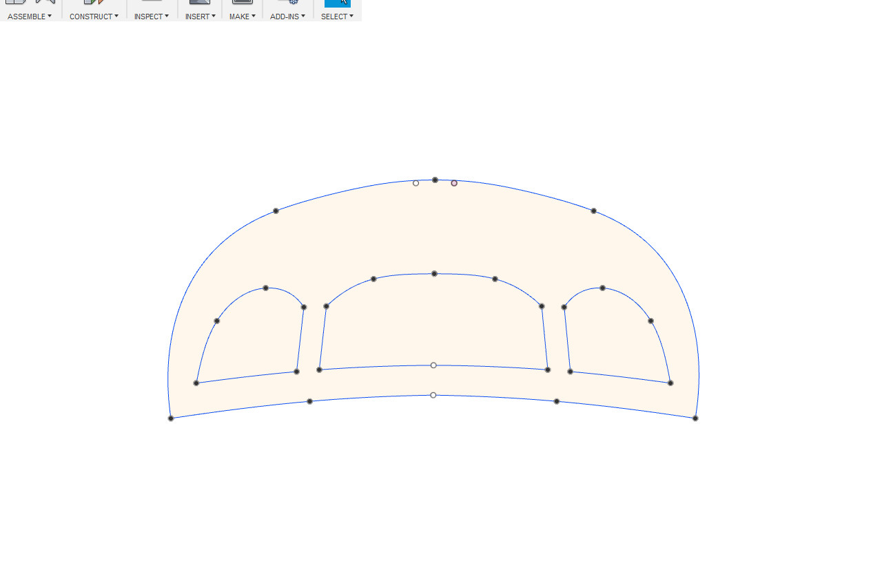
So what’s correct? As I mentioned at the start of this build log, I will be using the Sultana replica as the standard. Fortunately, I found a good picture of the Sultana’s transom at the website “829 Southdrive”. Picture by the website author “Baydog”.
From this picture, the windows should be fairly small, and the recess line is fairly low. That makes the Chapelle drawing the closer match.
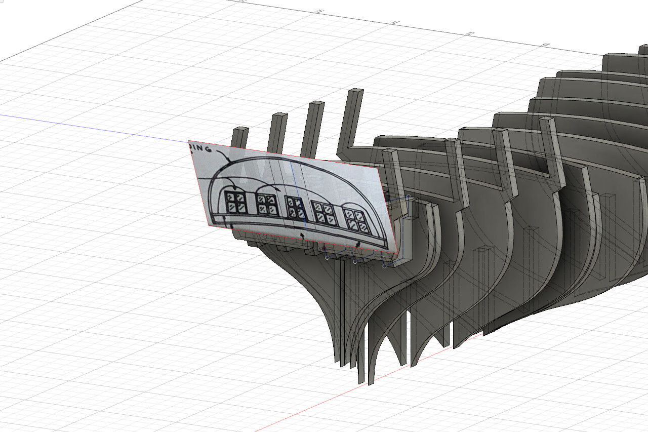
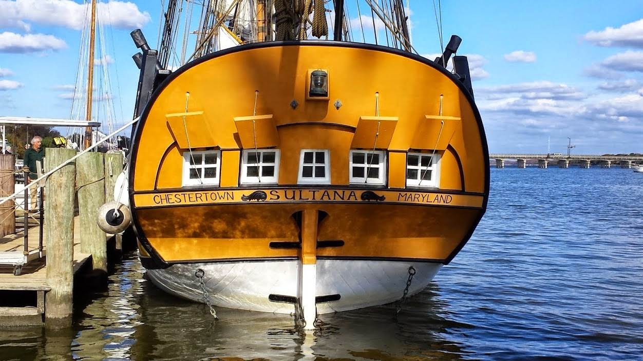
Following the Chapelle transom and the reference photo, I came up with these two sketches for the two pieces.
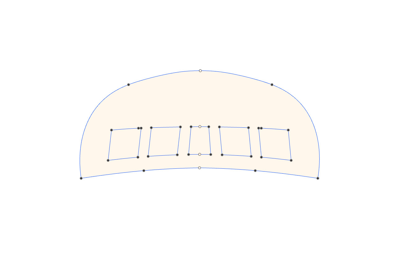
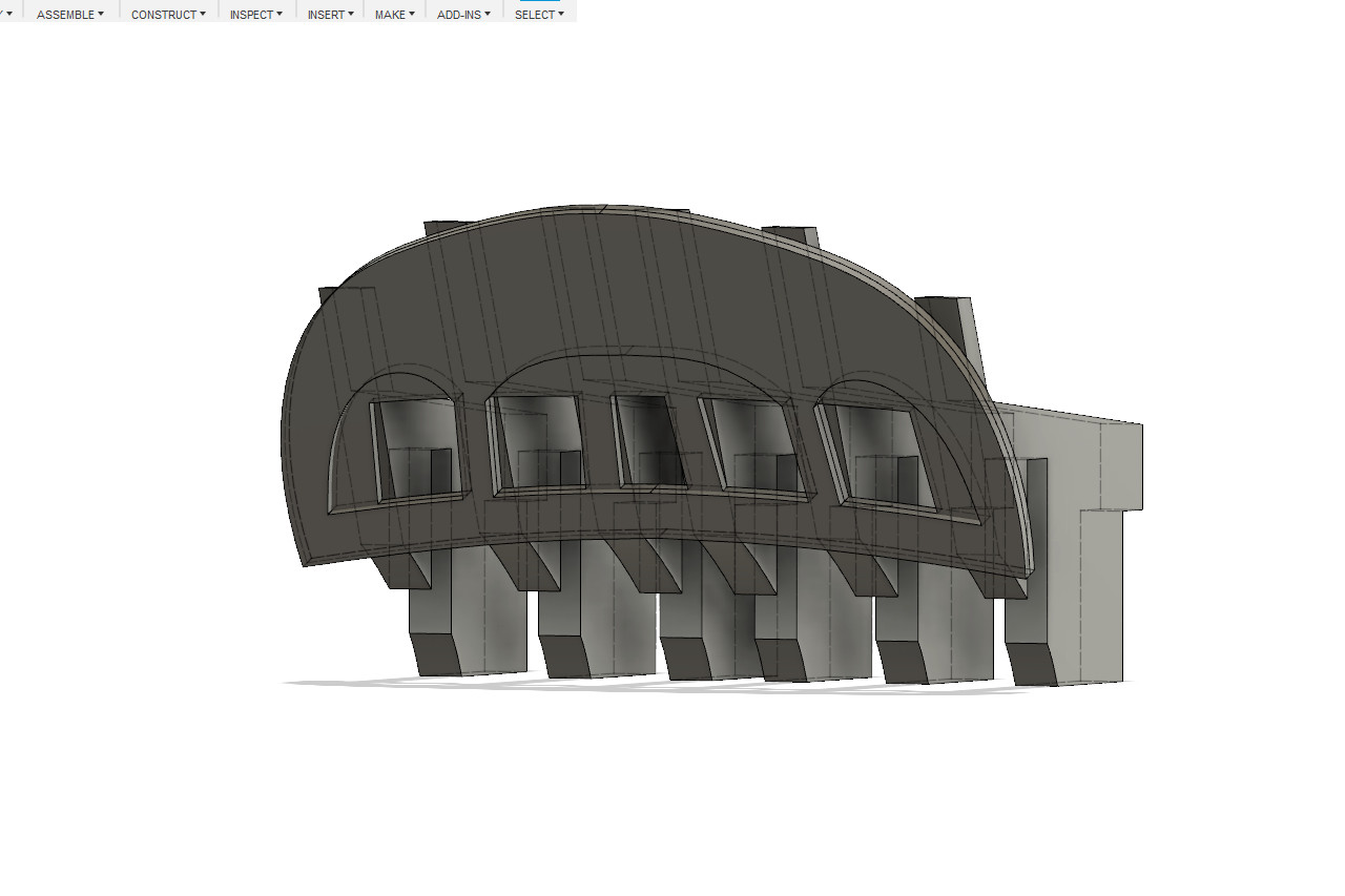
Solid parts were created in the 3D environment to see how they will look. (The real parts will be curved.)