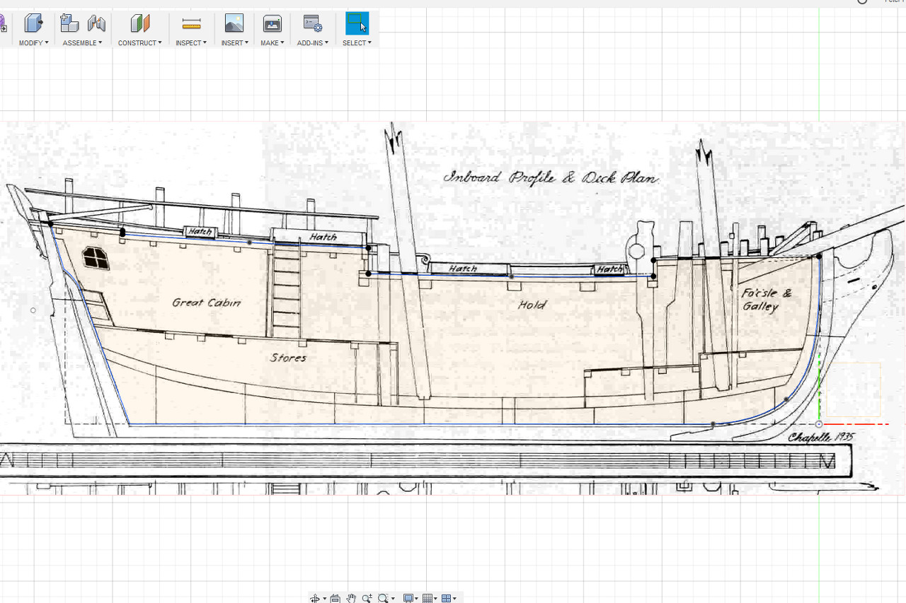
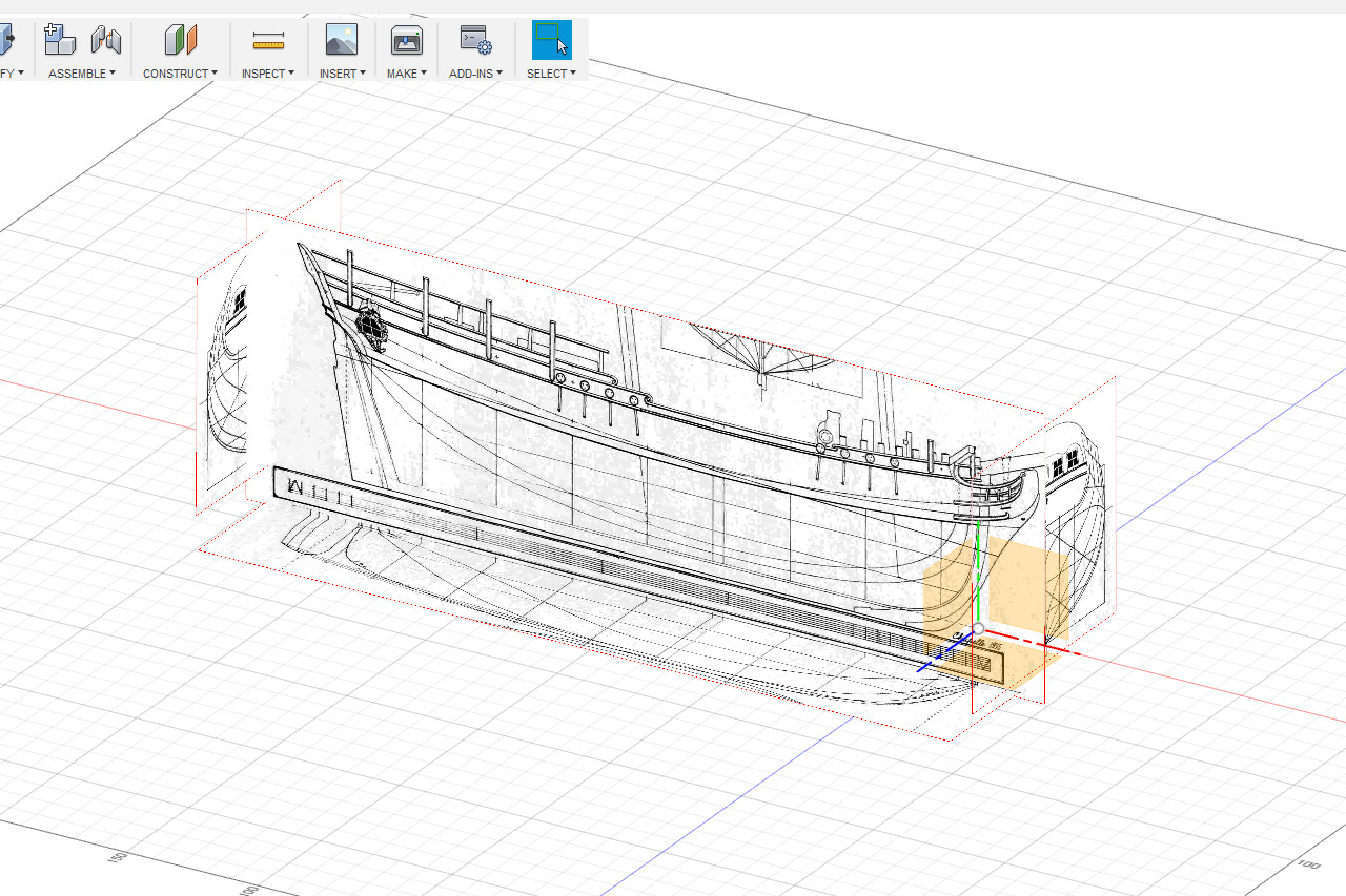
The next thing I need to figure out is the exact placement of the decks and the deck camber. I bring up the inboard profile image. Starting a sketch in the centerline plane, I trace the lines along the underside of the planking on each deck. The lines for the two innermost decks (main deck? and quarter deck?) are very slightly curved. The other two are just straight lines. The sketch continues alone the rabbet and back to the start. I’ll be using this sketch for the false keel laser cut piece. Notches for bulkheads will be added to it later.
Sultana build log – Part 6
In order to establish a good ending shape for the hull, I added one more curve at the stern. This is a little guesswork since it isn’t a line on the plans, but I think the shape is pretty close.
Sultana build log – Part 5
The sketching of lines continues with finding intersection points and then sketching fit point splines through those points. Here are the intersection points for the two waterlines, with the waterline planes visible.
Sultana build log – Part 4
Now I’ll create sketches of the various hull curves.
For the topmost line, I will create a curve following one of the bulwark lines on the plan. To ensure correct placement, I create a construction point at the tip of the bow, which will be used as a starting point for the curve. A fit point spline is created in a horizontal plane following the curve as viewed from above.
Sultana build log – Part 3
Step one is to bring the plans into Fusion 360 as canvas objects. The plans are checked to make sure that all lines are perfectly horizontal / vertical, and that lines in one view match up to the corresponding lines in a different view. The images have been scaled in the 3D environment to match the scale of the model (1:64 or 1 foot = 3/16″). The 3D origin is at the intersection of the baseline, the center line, and the forward perpendicular.